Pages

Wednesday, October 14, 2015

BOMBARDIER VISIT

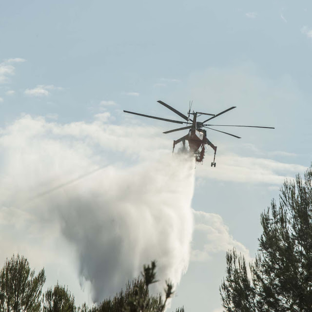
Here is one of the two Bombardier Super-Scoopers that visited here a couple of months ago.  I did a high-pass sharpening on the image.  I selected a high shutter speed because I was only going to get one chance with hand held images at 360mm focal length.  It worked because virtually ever one of the 150 or so shots I took were pretty solid ... but it did stop the props.


Thursday, October 1, 2015

WAR FACE

Our two 50# poodles are sweet tempered and calm.  But when they "fang fence" they put on their war face and have at it.  The action is fast and furious and you would swear someone would get hurt from the sound of the snapping teeth.  But there is never any damage.  They run and wrestle and fight by the hour and then nap just as hard.  They even have games of "midnight basketball" and go out at 03:00 to turn on the infra-red triggered lights in the back yard and have a "scrimmage".  Characters.  +Heidi Anne Morris 


Monday, September 28, 2015

JUST ANOTHER VIEW

I fixed some panel lines and Dzus fasteners and put in an indication of the canopy slide rails.  Getting the prop blur halfway right is tough for me.  It takes operations in PhotoShop that I am not happy with.  But at least the tip blur geometry is calculated by the programs.  I have to export the pixel image twice, with and without the prop and "diddle" things in PhotoShop.  But it is fairly believable.  This cloud scene looks more realistic as well.  


SPITFIRE FLYING AGAIN

The clouds were nice yesterday.  I played with prop blur treatment again.  It sure took a lot of experimenting to get anything near realistic with materials in C4D and it took some manipulation in PhotoShop even after that.  But at any rate the prop arc will now follow the 3d nature of the C4D treatment without external help.  Just reminded myself ... I have to add the canopy slide rails.


Wednesday, September 23, 2015

MORE MARKINGS

After researching some pictures I have added text markings to the Spitfire.  It seems that the Brits signified Walkways rather than "Don't Walk" regions and that the early Spitfire drank 100 octane gasoline and had an 85 Imperial gallon capacity (and got about 10 miles to the gallon at best).  I don't want anyone to think I have quit working.  I have also refined the landing gear so that it retracts properly and the landing gear cover is flush with the wing bottom when they are retracted.  I still need to cut a hole in the bottom wing surfaces for the landing gear cavities and I have found a Linda tutorial on Character Modeling that has told me more about doing that kind of thing than I have found anywhere else.  +Dale Jackson +Harley Harp +Åke Jon 


Sunday, September 13, 2015

44 YEARS AND COUNTING

I fired her up today after 3 years sleeping under a car cover.  A little 3 ampere battery charger overnight got the battery happy enough that it spun right off.  It is a one-owner car.  My wife's pride and joy.  People have often run her down to comment on the car.  It is probably the ONLY '71 XJ6 with a working air conditioner in the world ... which is to say not much of anything because the ventilation system is about as effective as you would expect from Brit machinery ... just roll down the windows ... if the GM knock off window regulators will work.  Hard to say how many miles are on it.  Upward of 200,000.  It has a Series III engine with all external Series 1 stuff ... carburetors, etc. but a workable alternator and a Series III fan.  I expect at 1,000 miles a year on a hard year it will see me forever.  Brand new paint and bright work polish although it has been sitting under a cover for 3 years and needs shined up again.  All it is missing is one backup light lens and I will have to fabricate one or find one scrap.  It even has new windshield seals.  Yeah, a lot of little things would need done to make it "show ready" but why bother.  These things are not a highly desirable collectibles anyway ... more of a curiosity.  Tires need air.  I will take her for a test drive and get them filled up and the old gasoline thinned out with some new stuff.  It can serve as my backup wheels.


Wednesday, September 9, 2015

HOT TIMES

We had a little excitement yesterday.  The temperature was 102F when a fire started about 1/2 mile west of here and a few hundred yards south in an open brush area known as Coyote Hills.  The fire spread in a strip from west to east just past the housing development south of me and it burned the better part of a mile.  We had a ring side seat and watched a veritable air force of helicopters and the "Super Scoopers" drop water.  Dozens of emergency vehicles and "lookie-loos" (sp?) used our street which is the closest E/W road from the fire that has access from both ends of the involved area.  The closest approach of the fire was perhaps 600 yards.  Here are some shots of the various aircraft involved.  No homes or lives were lost but things got pretty exciting.  I took about 150 pictures right from my front yard.

SUPER-SCOOPER DROPPING A LOAD

SUPER-SCOOPER ORBITING

SKY CRANE DROPPING A LOAD

SKY CRANE CLOSE UP AS IT WENT BY

SKY CRANE SHOWING HOW CLOSE THINGS WERE


Monday, September 7, 2015

GUN PORT TAPE

Actually it seems that the red covering over the gun ports was doped on fabric.  Apparently done for each flight.  To UV map that onto the wing surfaces (top/bottom) with Cinema 4d took 16 rectangles of red.  Each had to be positioned along the length of the wing as well as fore/aft and angled tangent to the leading edge.  They all have to "line up".  In PhotoShop (where the texture resides) that took a lot of layers.  Next problem was to make a version where the covering has been blown away when the guns fire.  I did that with a ragged brush and trial and error bouncing back and forth from PhotoShop to C4D and back again ... over and over and over.  I did all of that painting on one layer on top of the others so making the layer visible or invisible make an un-fired and fired version of the coverings.  Now, I am sure there must be a better way but I am struggling with the "sharp angle" that results at the leading edge of the wing as well as the top and bottom of the fuselage.  It may be that more lines have to be added to both.  It is also disconcerting that the UV mapping is fine until a subdivision surface is added to the wing at which point a stripe at the trailing edge on both the top and bottom is generated.  HUH?  I don't have a clue about that.  At any rate here is what the "after-firing-the-guns" version of the leading edge looks like.  All of the previous Spitfire images did NOT have the guns positioned properly and the guns would have shot up the propeller.  They are now positioned to the 3-view drawings.  There sure is a lot of weight away from the roll axis and the guns would have a lot of "parallax" out at 400 yards so I am sure they had to be bore sighted or the "spread" could have been rather large.  That technology and procedure must be interesting.  Today, just like in about '48 when I built a stick-and-paper model of one of these things, the asymmetry of that one "Lucas refrigerator" hanging under the right wing amazes me.  

I have included the "texture map".  I simply copied the UV map representation from C4D into PhotoShop and did the painting on layers.  Not the easiest thing in the world to do.


WING UV TEXTURE


Sunday, September 6, 2015

... "OR EVER EAGLE FLEW" ...

http://www.skygod.com/quotes/highflight.html


Friday, September 4, 2015

DUCT TAPE

The gun ports were covered with red duct tape (which kind-of blows the “NASA invented everything” theory since it predates NASA).  So this is getting to look like what one of these critters actually looked like going into battle.  I will have to make a “duct tape” version with a hole in the center after the guns have been fired and call one or the other version depending on the “scene”.  Same for wheels and flaps.  The guns were put in the wing where they would fit.  One, a pair and another single.  The spent casing chutes are under the wings and about the size of a big hand.  The early armament was .303.  Cannons came later.  Quite clearly this detail generation can go on forever and ever.  I have to work on a “prop-blur”.  I have added trim tabs and some other detail that cannot be seen in this view.  +Åke Jonsson +Dale Jackson +harley harp 


Sunday, August 30, 2015

VACATION

I had to take a vacation from the C4D Spitfire project.  I was burned out.  Today I did the camouflage for the rudder and the left side wing fillet.  Soon the only big remaining task will be the cavities for the wheel wells.  THEN I CAN START ANOTHER AIRCRAFT.  :-)  +Åke Jonsson +Dale Jackson +harley harp 

Thursday, August 20, 2015

BREAKFAST ON THE RANGE

Here is a light breakfast out on the range.  First, you have to have a 100 year old Griswold cast iron skillet that has been recently cleaned.  I can personally attest to the fact that this one was THOROUGHLY washed very recently.  Spring of 2010 as I recall.

Next thin-slice some double mahogany smoked slab bacon.  1/4 inch thick will do nicely.  For a dinner with grits 1/2 inch would be better.

Put the bacon in the skillet with a sliced up peach.  Two peaches might be better.


It is important that the chef is properly "calibrated" and up to the task.  The following picture shows one method of calibration.


Proceed to cook up the bacon adjusting the heat applied to caramelize the peaches by piling them on the bacon or visa versa.  The peaches will "sweat" into the "hog fat" to make a delightful mix.


Presentation is part of the meal.  Here we have chosen the finest Wedgewood paper plates from Costco.  The mahogany pan drippings are scraped onto the top.  Any left-over liquid in the pan can be used for hair pomade and will be relished by any camper nibbling on your ear after hours.


Saturday, August 15, 2015

SUBTLE FASTENERS and PANELS

Remember that I had black dots for the fasteners and black lines for the panel edges?  Here is the image.


This morning I did a little research and learned some things.  I knew I could change the nature of each row of dots but that would mean changing details on about a dozen layers in PhotoShop one at a time.  I took all of those “text” layers made up of “period”, “space”, period and put them into a group.  I then changed the “blending mode” for that group with the underlying color layers to “soft light” and varied the opacity (magnitude of the effect) to make the Dzus fasteners more subtle rather than just solid black dots.  Soft light doesn’t change the color but varies its intensity at the dot positions.  The effect is to make the fasteners look like they had been overpainted (which they are) and then worn a bit.  I put the panel edges and things in another “group” and can vary how “intense” that effect is independently.  The fasteners and panels can be adjusted independently and all at once.  There are about six “regions” involved in the so-called UV map which makes the 3d surface into a squished 2d version and the fasteners have to be positioned on the panels by making movements in PhotoShop and checking the rendering in Cinema 4D by saving the PhotoShop image and then reloading it into C4D and rendering.  But it does all work.

What remains to be done is to change the scale factor on the Dzus fasteners right at the spinner in the aircraft long direction so that the fasteners are not stretched by the curvature.  No big deal.  I now think I have one of many possible workflow scenarios figured out to simulate fasteners and panels.  There is a lot more that can be done with PhotoShop as well as by making so-called “bump maps” for the textures in Cinema 4D.  This can go on and on forever but the results so far have been very encouraging.  An image of a subtle treatment of the Dzus fasteners and panel edges is shown below.


Thursday, August 13, 2015

LONG STRUGGLE

It has been a long struggle and there are still DAYS of work left to go on the Spitfire project.  It certainly has been a learning exercise.  Yesterday I lost all of my work on the fuselage camouflage simply because the documentation for Cinema 4D does not explain the STRATEGY of data set storage and manipulation but, instead, gives you a cook book and leaves you to web sources for some meager knowledge.  Well, I have mostly recovered and certainly know what not to do the next time.  It is looking good ... from far, but far from good. I need a rest.  Although I haven't used it I know what the "to do" list feature in the software is for.  +Dale Jackson +Åke Jonsson +harley harp 

Wednesday, August 12, 2015

FUSELAGE CAMOUFLAGE

I can't hit the right simile to use about getting the camouflage (mostly) onto the fuselage.  Is it like "birthing a horse" or maybe a breech birth with a porcupine.  When Cinema 4D, Illustrator and PhotoShop are all involved simultaneously and it is CNTL in one program and ALT in another to do the same operation plus four or five file types I think I can appreciate how a master juggler feels.  Yes, there is a goober here and there and, yes, the wing filet has not been painted and, yes, there are many details yet to attack ... but I am now thinking that maybe the target date for completion (these things are never really complete) might get pulled back from Halloween to Labor Day again.  And, oh, the video driver card and its software gets in the act and a soft start of the computer DOES NOT solve that.  It takes turning off the house circuit breakers and turning them back on.  :-)  :-)  There is apparently zero video card "standards" that work properly all the time.  And Illustrator doesn't like the driver version ... I NEED to spend two hours fighting that.  And just to make things totally impossible C4D uses the mouse wheel to magnify and Adobe hasn't figured out yet that approach has now become an industry standard.  When the day comes that there is ANY cooperation between software companies I will be a firm believer in miracles.  What fun.  But it sure makes the hours fly.  Next: the fuselage side markings.


Tuesday, August 11, 2015

DIHEDRAL

I just couldn't stand the flat wing any longer.  Although I still have no idea how to "munch" a hole into the bottom of the wing to install a wheel well and making the wing asymmetric may create more work later on, I just had to "bend" the wing to create dihedral.  Even that was more complexity than I thought it would be but it got done.  I think the beast looks much more airworthy with proper dihedral.  I continue to be amazed that the Brits could manage to make these things fly straight with a Lucas refrigerator (just kidding) under only one wing.  (Why do the British drink their beer warm?  Because Lucas makes their refrigerators.)

I confess.  I DID save the unbent wing along with the bent version in case I run into trouble later on.

I was pleasantly surprised to find how easy it was to create a five-spoke wheel hub with Cinema 4D.  Yes, I know, for those with a little peer or formal schooling this is all hypernerbalicious simple (take-off on Supercalifragilistic).  But for this unschooled 3d savage it is delightfully easy without help.


And even from the underside looking up the dihedral makes things look more natural.  PLUS ... I am sure the thing might even fly instead of instantly entering a flat spin.  Don't you just love the stylized Hoover vacuum sweeper hung under the left wing for an oil cooler?  (I am allowed to poke fun at the Brits.  After all, at one time I actually had 44 cylinders worth of British cars all running at the same time ... which may be a candidate for a world's record.)

Monday, August 10, 2015

UNDERSIDE DETAIL

I have hung the Lucas refrigerator radiator under the right wing, the oil cooler under the left and the air intake in the center.  What comes next?  Just too many things to do to contemplate.  Maybe work on the wheel rim, huh?  Yes, the wing is still flat and the flaps should be down.  More and more details.  Wheel wells are a really big issue.


Sunday, August 9, 2015

CINEMA 4D SPITFIRE FOR SUNDAY

ALRIGHT.  I figured out why C4D screamed about missing files and fixed that.  It now renders without complaint.  I revisited the geometries on the landing gear and created wheel covers and made them the same goose-egg-blue as the underside.  I will have to map different colors for the inside and outside and figure out how to make multiple extrudes to create the inside detail.  Later.  For the rest of the day I MAY work on the radiator or wheel hubs or just veg-out.  I have some Budweiser so maybe a veg-out afternoon is in order.  The "BIG DEAL" is going to be munching a hole in the bottom of the wing for a wheel well.  That one eludes me so far.


Saturday, August 8, 2015

BODY PAINT AND UNDERSIDE

WHAT A STRUGGLE.  I must say ... I have never seen anything that is more grotesquely over-complicated than body paint in Cinema 4D.  I blasted through the obfuscation with unbelievable stress.  Still isn't right.  Somehow the program thinks the color for the right aileron is not available and is hidden down in "User" "Documents" which denies me access.  Haven't blasted through that yet with Microsoft and C4D both in series with progress.  There will be a way but beats me how for now.  I am ready to start on the tail feathers and fuselage.  I put landing gear place keepers in the file taken out of one of my practice sessions.  I picked the "goose egg blue" right out of the Audubon book (just kidding).  No dihedral added yet.  This kite would be totally unstable the way things are.  I thought I was kidding about getting the project more-or-less done by Labor Day.  I have revised my estimate now to Halloween.  Fitting.  +Dale Jackson +Åke Jonsson +harley harp 


Thursday, August 6, 2015

TEXTURE MAPPING

Oh, me!!  I am pretty badly disconnected from the texture mapping.  HOWEVER, I stumbled around and figured out how to create a non-symmetric object out of the symmetric object it once was.  I then stumbled around A WHOLE LOT MORE to get the frontal projection of a JPEG PhotoShop image to line up with the UV map in Cinema 4D.  I put a second roundel on the left wing.

The result is the Spitfire now has a left and right camouflage pattern like it "should-oughter".  The ailerons are separate entities and know nothing about the wing material/texture so I suspect I will just "body-paint" them by hand ... if I can get a good hard brush edge.  I used "frontal" projection which I believe will work for the wing and tail feathers but probably not for the fuselage.  Then again maybe I can "pre-distort" the texture map in PhotoShop so that it will do a reasonable wrap onto a frontal projection of the fuselage.  But maybe I should struggle with "unwrapping" the fuselage if for no other reason than to induce another migraine.  There are several ways and I am sure I will wind up exploring all of them.

In any case ... here is the state of the camouflage treatment at this brief instant in time.


Wednesday, August 5, 2015

ROUNDELS

Here is a try at generating roundels for the wings.  The colors might not be that accurate but it has been an experience.  Next comes the left/right wings, ailerons, fillet and the fuselage.  I am encouraged. +Dale Jackson +Åke Jonsson +harley harp 


TIME FOR CAMOUFLAGE

I used the new version of ILLUSTRATOR to trace out camouflage patterns from 3-view drawings of a Spitfire on the web.  I searched around and found a sunlit image from the RAF museum and sampled the colors with the ILLUSTRATOR eye-dropper.  The spline-draw tool (curve) in ILLUSTRATOR is much better than the pen tool but also about as obtuse and non-intuitive (but then that is probably just me).  I took the JPEG version of the ILLUSTRATOR camouflage pattern and put it onto a texture in Cinema 4D and dropped that onto the symmetric wing object knowing that it would be (improperly) mirrored onto the opposite wing.  I have not coped with the fillet or ailerons that have to be handled separately or the side views of the fuselage.  It will all come as I slowly learn this multi-program monster.  For now I am ticked as much as I ever get tickled.  I know I am doing this in a not very efficient manner but I am learning.  This is but a start.

Thanks again go to Anders Lejczak http://www.colacola.se for donating non-commercial use of bits of his files.  I hope I can repay the favor someday and I will re-created anything borrowed from scratch.

Sunday, August 2, 2015

COMING IN ON ONE AILERON AND CROSSED CONTROLS

+Dale Jackson +harley harp 
Things do go slowly.  I have added a wing fillet.  It started life as a cylinder and got trimmed down to a concave 90 degree segment and then the orthogonal dimensions adjusted and the axis of 10 "cuts" moved to put each slice against the fuselage and wing on the two ends.  It will take some adjusting yet ... particularly under the fuselage at the end.  However, it doesn't look too bad and it certainly makes the aircraft look much more "natural".  I cut out a wing segment and made it into an aileron.  The mating "hole" in the wing trailing edge is yet to be done.  I have figured out how to do that without ending up with messy n-gons all over creation.  The "big deal" yet is to cut a cavity in the bottom of the wing for a wheel well.  I did it once and promptly forgot how.  I saved the file so I can use it to recall.

I have been working in "symmetry" for the most part.  Problem is: how do I do left and right details?  I suspect the procedure is to discard the "symmetry" half and then reproduce the remaining half mirrored and simply place them against each other so there are left and right halves that can be unique.  Now, you would think there would be a way to take a "symmetry" piece and preserve all of the points but make it a single element so that a different "paint" can be applied to the left and right.  I will bet there is but it is hidden very deep and things like that are NEVER covered by Lynda or others ... too simple in one respect and far to advanced in another.  Most of the tutorials are aimed at the most elemental operations.  Further, the "search" engines in "help" key on single words.  No context searching.  It is not exactly "google-ish".

I have put in and taken back out dihedral.  (It is quite interesting that the google/blogger spell checker does not recognize dihedral.  This happens to me a lot with my vocabulary.)  I want to keep the wing axis flat for working on the wheel well for now.  The control surfaces are turned for effect.  There is only one aileron and it is at cross purposes with the rudder ... the way to induce a spin.  Things are a bit bumpy and lumpy here and there but I verge on the ecstatic that I have persevered to this point.  The program is indeed quite "friendly".  All of this would be quite easy with just a little peer help ... like in a graphics arts organization.  But for a "lone wolf" it has had its painful moments.  (Actually more of a "Lonesome Polecat" re: Al Capp, "Lil' Abner" for you that remember the 50's like they were yesterday.)

AHA.  A bit of research reveals that the mesh convert command "current state to object" does indeed take a symmetry object and convert it into a single object (keeping the symmetry object).  That solves my left/right "painting" problem and allows me to make left and right variations to an otherwise symmetric "thing".


Tuesday, July 28, 2015

PILOT TIME

I have taken advantage of the incredible generosity of Anders Lejczak http:www.colacola.se to download some of his C4D shared files.  Many thanks.  Follow the link to his amazing work.  And that is where the pilot came from in these images.  Many thanks.  There is a great deal to do yet on my model but it is coming slowly. +Dale Jackson +harley harp 


Sunday, July 26, 2015

PICKLE BUTTON in CINEMA 4D

Now there is a “wheel” … which was an oval, more-or-less, a yoke/stick and a pickle button.  Rudder pedals next and some frill for the sides of the cockpit and then I need to think about a pilot.  This is addictive but the nice thing is: you can do all of the detail that you wish you could have done when you were 15 years old and don’t have to get totally frustrated with destroyed work.  You can always “undo” and just do it over.


INTERIOR PLUS GUN SIGHT

The gun sight is a "reasonable facimile".  The dash from a picture.  Yes, they simply wrapped something like garden hose around the metal parts to provide a tiny bit of protection to the pilot's face.  I made them brown.  The front teeth need removed from the adjustment "gears" but I liked how they looked so much I left them for now.  I DO hope there was precious little Lucas electronics/relays.  That would be a worse threat than the Luftwaffe.  


Friday, July 24, 2015

CONNOLLY LEATHER, BUT OF COURSE

What else?  Maybe Bridge of Weir in a pinch.  I'll bet about as comfortable as sitting right on the steel ... maybe a bit better.  But spot on Brit.

OK.  That is it.  I quit for the day.  C4D has had its pound of flesh.


GUN SIGHT

The sight mount needs to be a tube instead of a cylinder and a projection lens put in it.  The optics were just like a modern "red-dot" pistol sight and projected a virtual glowing ring, cross hairs and dot onto the target plane.  The position was largely independent of the pilot's head position taking that element out of the equation.  The diameter of the ring was adjustable (I believe) so that when the pre-defined target wingspan fit the ring it was time to "mash the pickle" under the left thumb and walk the tracers onto the target.  Some of the sight screens were round and some rectangular.  I might make this one rectangular just to make the job of creating a mounting bracket easier.

Blogger is also driving me nuts.  Why is it that the picture size posted is different than that selected and how is the default font changed?  The "instructions" and "results" seem to live in different universes.


GUN SIGHT

This is just a place keeper.  I need to make the base a tube instead of a cylinder and then add a projection lens in the center.  It also needs a mounting bracket for the "hud" plate. These things worked just like a "modern" red-dot pistol sight.  The projected ring, cross-hair and dot seen by the pilot did not move on the target as the head moves (within limits) taking the pilot's head position out of the sighting equation to a large extent.  The projected diameter of the image was adjustable (I believe) so that when the enemy aircraft wing span was near the image diameter it was time to "mash the pickle" under the left thumb and walk the tracers onto the target.  The sight image would not be easily visible from outside the cockpit.  The disc was optically arranged to reflect the image from the upward-facing projector optics horizontally at the pilot.  All of this detail could go on forever.  There has to be a stopping point.  Some of the sighting surfaces were round.  Some square.  A square mounting bracket would be easier so the surface might get changed to square just to make it easier.

Blogger is also driving me nuts.  Why is the image different when posted than when set up in the dashboard?  How can the default font get changed?  What happens and what instructions say should happen do not appear to exist in a mutual universe.


THE ARMOR PLATE ARRIVES

I got up at 06:30.  I love the early mornings.  Makes the day nice and long.

This morning I created the armor plate that goes immediately behind the pilot.  When they said in novels that they could feel the strike of bullets against the armor plate it was because the bucket seat is right against the plate.  The plate was apparently a hefty chunk of steel plate just cut to shape with a power saw.  Straight across the top just at the top of the head rest and straight down just inside the cutout in the bulkhead for rearward visibility.

I also re-did the antenna and insulator.  The antenna mast was not round but more oval and it was not straight sided but tapered as a curve and pretty tiny at the top.  The insulator was a frustrated cone.  (Frustrum of a cone).  (The idiot spell checker doesn’t understand frustrum.) 

I am kind-of liking the dirty German camo color with the mottling even though it is nothing like the Brit Spitfire camo scheme.  If I ever figure out how to eliminate the one n-gon that totally messes up the UV mapping for the fuselage I will give C4D “body paint” a try with an educated guess at the shape and color of the rigidly adhered to paint scheme.  (If and when.)  I can delete the offending polygon and put in a totally unrelated substitute as a stand along but somehow that is not hard enough for me.  There just be a way.  Surely.

I find the “U,V” thing amusing.  Since 3D axis are named X, Y, Z by convention, the mapping of 3D onto 2D used U, V from U, V, W, X, Y, Z.  Poor old W got skipped.  Could it have been reserved for mapping 4D into 3D?  Was there some reason for it or was the “inventor’s” wife’s names Eunice Victoria?  J  J


Thursday, July 23, 2015

NEXT COMES THE SPINNER

Since the fuselage is looking reasonable it was time to add a spinner. 

I have one nagging problem.  Just at the shoulder level to the pilot a polygon of the fuselage is all alone joined to the rest of the fuselage on only two edges.  That causes C4D to throw a "hissy fit" and generate an n-gon.  Now, everything renders and looks fine.  But the UV map of the surface is all "goobered up" because the adjoining polygon has five points.  I have not discovered how to solve that problem and it "nags" on me.  I have tried all manner of things but any action makes things worse and not better.  Suggestions?


NOISY GRUNGE

I added a squarish grungy noise to a desaturated khaki green color to get the effect in the image.  The color might feel at home on a FW-190 or ME262.  Cinema 4D certainly is rich in features and I will be busy for at least a decade.  I think I will have to put my copy of C4D in my will.


Wednesday, July 22, 2015

NOW IT IS BULLET PROOF GLASS TIME

I added a tie between the frame for the bullet proof glass and the rear frame for the windscreen Perspex.  I also added a rudimentary antenna, insulator, rear view mirror and post.  More and more detail.  Mostly place-keepers for further refinement but things look better and better.  The bullet proof flat windscreen has thickness and it is obvious in the rendering.  I am learning but it is slow.  The rear part of the canopy will "slide" properly although it still squeaks and I haven't found out how to add grease in Cinema 4D.  :-)  :-)


Tuesday, July 21, 2015

CANOPY FRAME


The procedure is to duplicate Perspex canopy object.  Make “cuts” through it to create points at the right places and enough of them so that the polygons that make up the surface can be deleted leaving only the surfaces where the canopy frame would be.  The “color” of the frame would then still be Perspex.  So I had to create a new color/texture just for that section.  The problem is: I am not adept at avoiding so-called n-gons (polygons with more than 4 sides) which are “badness”.  I eliminated a couple of them but there are still more.  I have to research that.  I then made the canopy frame a “subdivision surface” so it renders nice and smooth instead of with the jagged point-to-point of the bigger polygon surfaces that are not “smoothed” in the process.  The result is shown.  Yes, it needs a lot of editing but it is a breakthrough for me.  Now I get to stumble around and read a bunch of irrelevant tutorials but eventually I will find “answers”  

CINEMA 4D

THE CINEMA 4D SPITFIRE PROJECT


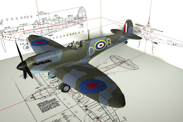
I will just mess around and try this on for a blog of working with Cinema 4d and my attempt to build a model of a MK1 Spitifire.

Cinema 4d is a fairly friendly program although complicated and full of "hidden" ways to get to what you want to do.  But that is not unusual at all.  Microsoft has while divisions devoted to obtuse menus and feature access.  :-)  :-)

So here are some pictures showing where I am at the moment:

3 VIEWS DOWNLOADED AND FORMERS CREATED
At this point "blueprint' drawings have been downloaded from a web source and put into a 3d working "stage".  A multi sided cylinder has been added and the former "cards" placed.  If anyone is interested I will explain all of this from my poor understanding of how it is done leaning from web sources and Cinema 4d tutorials.


THE CYLINDER BY ITSELF SHOWING "CUTS"

Here the lines describing the cylinder have been "cut" using the "knife" tool.  Points are created that are then pulled inward to match up with the shapes on the former cards.

THE ROUGHED OUT FUSELAGE

At this point a rough fuselage has been created and some details added.  Sounds easy.  Well, at this point I am into Cinema 4D to the tune of a couple of hundred hours.  The learning curve is not real steep but it is pretty complex.

CANOPY CLOSE UP

I have created a frame for the bullet proof front glass.  Next step will be to create the bubble section frame.  Looking at web sources, this approach can eventually lead to a flying scene with rather startling realism.  In another file I have created a wing (which I will re-do) and the landing gear and gear well, wheels, rudder/elevator, ailerons, spinner, exhaust, and other details.  It is all for practice because virtually everything gets re-don several times to refine technique and detail.